Object Settings
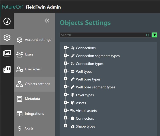
The Object Settings page allows you to modify, delete, or create new default object types for any new projects created for your corporate account. The available Objects are comprised of the following categories:
| Object Type | Description |
|---|---|
| Connections | This is the pipeline, cable etc. object type |
| Connections Segment Types | This is segment object that can be applied to Connection object |
| Connections Types | This is comprised of standard connection, risers, jumpers objects etc. |
| Well Types | This is the Well object that can be used for metadata assignments to wells |
| Well Bore Types | This is the Well Bore object linked to parent Well object |
| Well Bore Segment Types | This is segment object that can be applied to Well Bore object |
| Layer Types | Assign Metadata for the various types of Layer objects |
| Assets | Assign Metadata for the various types of Assets |
| Virtual Assets | Create Virtual Asset objects e.g. non visible assets |
| Connectors | Create new connector objects |
| Shape Types | This is the Shape type object that can be used as metadata assignments to shapes |
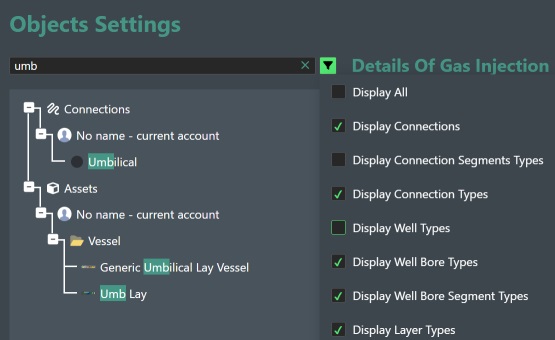
You can use the Search bar on top to search in any of the defined object groups. Clicking on the search funnel icon will allow you to select which object categories should be displayed in the search.
Object Commands
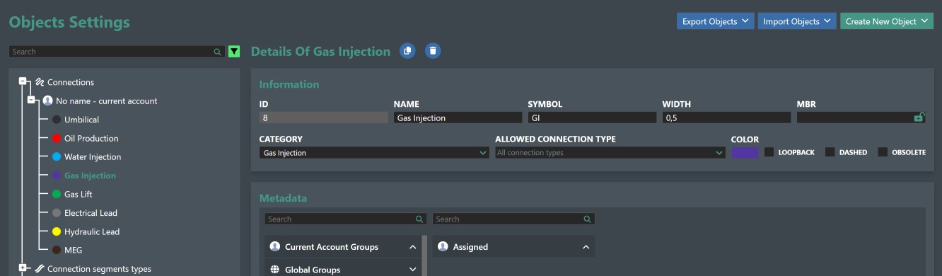
You can expand an object list by clicking + for e.g. Connections as shown below and it will display a list of all the current entries. For connections all the system defined connections will be displayed first, and the Information panel on the right will update accordingly:
Move - You can rearrange the tree list order by clicking a list entry and holding in the mouse button and then moving it to a different position.

Clone - Click on the "copy" icon as shown above to create a clone of the selected object with the same settings. A new entry will appear at the bottom of the list with the "- clone" postfix to the original object name.
Delete - You can delete a selected object by clicking on the trashcan icon. A dialog box will prompt you to confirm as this action in not reversible
Create New Object
To create a new object you click on the Create New Object button which will the display the list of the supported object types as shown here:
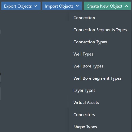
Then select the object type you want to create from the list. This will generate a new entry in the corresponding object category.
Connections Settings
This allows you to modify or create new default connection types for any new projects created for your corporate account. All users can also add project specific connection types on a per project basis afterwards.
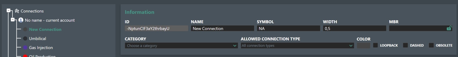
To modify an existing connection, you can change the connection Name, Symbol, Width, MBR, Category, Allowed Connection Type, Color, Loopback, Dashed and Obsolete properties.
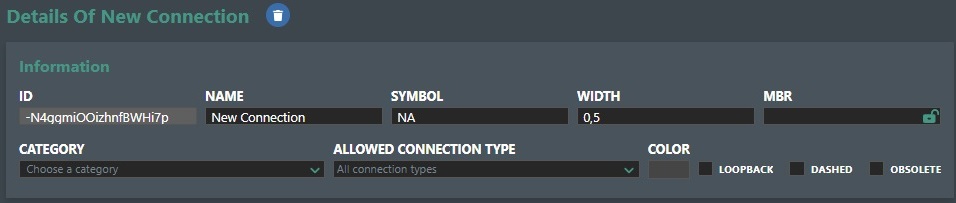
ID - This is the unique system ID assigned to the new connection type. Note! This is not changeable.
The connection properties you can change are as follows:
-
Name - Type in the desired name of your connection type.
-
Symbol - Type in the symbol designation for the connection e.g. GI for gas injection.
-
Width - Specify the width of the connection. Valid inputs between 0,1 and 2.
-
MBR - If you will be using the Bend Radius design tool you can specify a default bend value radius here. You can also lock this value by cliking on the small padlock icon at the right hand side of the input field. Click again to unlock it.
-
Category - Select the category of your connection e.g. Umbilical, Production, Water Injection, etc.
-
Allowed Connection Type - Select the connection type for your connection from the drop down list e.g. Riser, Jumper, Straight, etc.
-
Color - Use the color picker dialog to select a new color for your connection.
-
Loopback - Check this is the connection type should allow itself to be connected back to itself.
-
Dashed - Check this is you want the connection drawn as a dashed line.
-
Obsolete - Check this box if this connection type is now obsolete. If you click on the "Refresh Obsolete Connection Warnings" button then all projects using this connection type will have this flagged visually as an obsolete connection.
Clone - You can clone a Connection Type by clicking on the clone icon.
Delete Connection Type - Press the trash can icon to delete the created Connection. You will be asked to confirm the deletion.
MetaData - This section allows you to search and assign the available metadata definitions to the connection type. See the Meta data section for more information.
Connection Segments Types
You can now define “Segments” on a connection meaning that it can be comprised of multiple segments. This can be used to e.g. assign various segments of a connection for rock dumping, trenching, or if a connection is assembled with different types/materials e.g. parts of a mooring line could be chain etc. In this screen you can define various segment types and assign metadata to them.
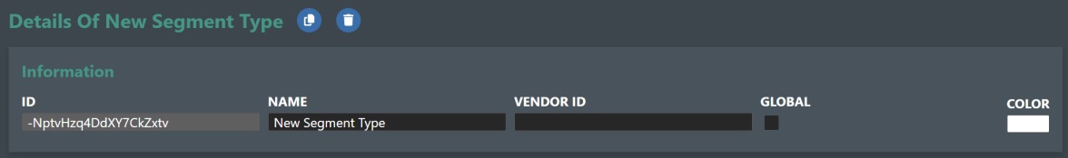
After creating a new object of Connection Segments Types you can set/change the following:
-
ID - This is the unique system ID assigned to this object. Note! This is not changeable.
-
Name - Type in the name for your connection segment type.
-
Vendor ID - You can assign your desired VendorID in this text field.
-
Global - Check this box if you want to make the segment type global for all Accounts.
-
Color - Use the color picker dialog to select a new color for your segment.
Clone - You can clone a Connection Segment Type by clicking on the clone icon.
Delete Connection Segment Type - Press the trash can icon to delete the created Segment. You will be asked to confirm the deletion.
MetaData - This section allows you to search and assign the available metadata definitions to the connection segment type. See the Meta data section for more information.
Connection Types
This allows you to define or edit Connection Types or connection systems if you will. By default, the following connection types or systems are defined:
- Standard
- Riser – Lazy Wave - This is formula based lazy wave calculation.
- Riser - Catenary - This is a formula based catenary calculation.
- Riser - Taut - This is a formula based catenary calculation.
- Jumper – Horizontal Z
- Jumper – Vertical M
- Jumper – Vertical N
The default types also have a predefined “Render As” option e.g. how the connection will be represented graphically on stage.
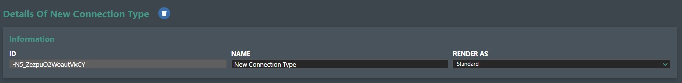
After creating a new object of Connection Type you can set/change the following:
-
ID - This is the unique system ID assigned to this object. Note! This is not changeable.
-
Name - Type in the name for your new connection type.
-
Render As - Select how it should be rendered on stage by selecting from the drop down list. Standard is the default render type e.g. rendered as a classical connection.
Clone - You can clone a selected Connection Type by clicking on the clone icon.
Delete - If you are the account Admin you can delete a connection type by clicking on the thrashcan icon. Other users will not see this option. A dialog will appear and prompt you to confirm the delete action as this cannot be undone.
To learn more about how to use the available Connection Types and their respective parameter settings please see the Connection Types section for more information.
By creating a new Connection Type or system you can then use it to discriminate metadata when creating new meta data types for “Connections”. See the Meta data section for more information.
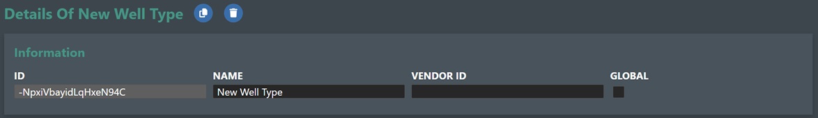
Well Type Settings
The Well Type object allow you to create different well types for your account that you can assign to your manually created or imported wells. More importantly this means you can assign Metadata definitions for your Well Types. This is useful if you need to add user configuration or input attributes for wells in your project. This could be for costing purposes or for defining data needed for integrating with external Drilling & Well software such as e.g. ProWell Plan and Oliasoft.
-
ID - This is the unique system ID assigned to the new well type. Note! This is not changeable.
-
Name - Enter or edit the name of the well type entry in this text field.
-
Vendor ID - You can assign your VendorID in this text field.
-
Global - Check this box if you want to make the Well Type global for all Accounts.
Clone - You can clone a selected Well Type by clicking on the clone icon.
Delete Well Type - You can delete a selected well type by clicking on the thrashcan icon. A dialog box will prompt you to confirm as this action in not reversible.
MetaData - This section allows you to search and assign the available metadata definitions to the Well Type. See the Meta data section for more information.
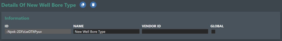
Well Bore Type Settings
The Well Bore Type object allow you to create different well bore types for your wells that you can assign to your manually created or imported wellbores. More importantly this means you can assign available Metadata for your Well Bore Types. This is useful if you need to add user configuration or input attributes for well bores in your project. This could be for costing purposes or for defining data needed for integrating with external Drilling & Well software such as e.g. ProWell Plan and Oliasoft.
-
ID - This is the unique system ID assigned to the new well bore type. Note! This is not changeable.
-
Name - Enter or edit the name of the well bore type entry in this text field.
-
Vendor ID - You can assign your VendorID in this text field.
-
Global - Check this box if you want to make the Well Bore Type global for all Accounts.
Clone - You can clone a selected Well Bore Type by clicking on the clone icon.
Delete Well Bore Type - You can delete a selected well bore type by clicking on the thrashcan icon. A dialog box will prompt you to confirm as this action in not reversible.
MetaData - This section allows you to search and assign the available metadata definitions to the connection segment type. See the Meta data section for more information.
Well Bore Segments Types
You can now define “Segments” on a Well Bore meaning that it can be comprised of multiple segments. This can be used to e.g. assign various segments of a Well Bore for casing, completion, or if a well is assembled with different types/materials e.g. parts of a wellbore could be gravel pack or sand screens etc. In this screen you can define various segment types and assign metadata to them.
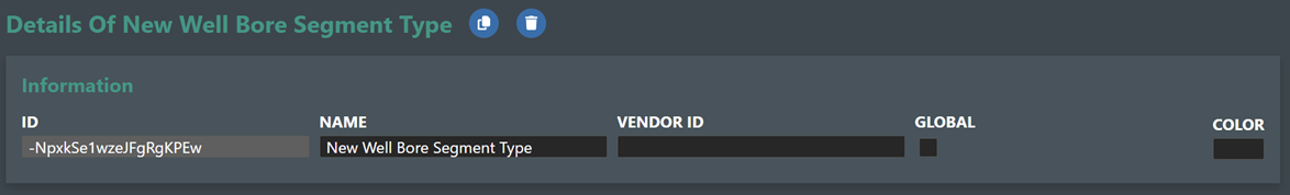
After creating a new object of Wellbore Segments Types you can set/change the following:
-
ID - This is the unique system ID assigned to this object. Note! This is not changeable.
-
Name - Type in the name for your connection segment type.
-
Vendor ID - You can assign your desired VendorID in this text field.
-
Global - Check this box if you want to make the Well Bore Type global for all Accounts.
-
Color - Use the color picker dialog to select a new color for your segment.
Clone - You can clone a selected Well Bore Segment Type by clicking on the clone icon.
Delete Connection Segment Type - Press the trash can icon to delete the created Segment. You will be asked to confirm the deletion.
MetaData - This section allows you to search and assign the available metadata definitions to the connection segment type. See the Meta data section for more information.
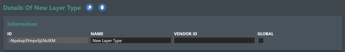
Layer Type Settings
The Layer Type object allows you to assign available Metadata for the various types of Layers. This is useful if you need to add user configuration or input attributes for e.g. 3D surfaces in your project. This could be for defining data needed for integrating with external software related to e.g. reservoirs. An example would be to define reservoir pressure etc.
-
ID - This is the unique system ID assigned to the new layer type. Note! This is not changeable.
-
Name - Enter or edit the name of the layer type entry in this text field.
-
Vendor ID - You can assign your VendorID in this text field.
-
Global - Check this box if you want to make the Layer Type global for all Accounts.
Clone - You can clone a selected Layer Type by clicking on the clone icon.
Delete Layer Type - You can delete a selected layer type by clicking on the thrashcan icon. A dialog box will prompt you to confirm as this action is not reversible.
MetaData - This section allows you to search and assign the available metadata definitions to the Layer Type object. See the Meta data section for more information.
Virtual Assets
Virtual assets are non-visual descriptions/objects that can be assigned metadata and can be linked to other assets, connections, and connectors. Examples here could be the creation of virtual fluid assets that can be assigned to pipelines for running simulations, non-visible topside equipment such as pumps that needs to be assigned a cost and appear in bill of materials etc.
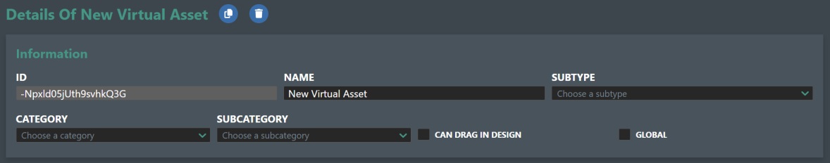
-
ID - This is the unique system asset ID for the virtual asset. Note! This is not changeable.
-
Name - Enter a new name or edit the name for the selected virtual asset.
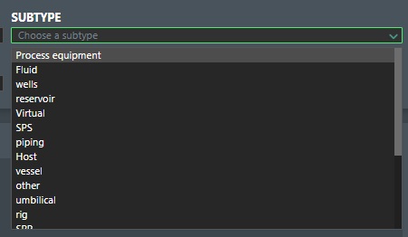
-
Sub type - Drop down list allows you to assign a type to it e.g. SPS, piping, rig, vessel etc. as shown here:
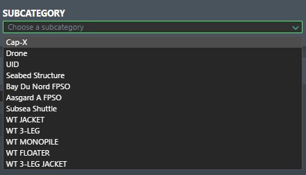
- Category - Assign it to a category as e.g. Manifold, Template, XMT etc. as shown here:

- Sub-Category - Assign it to a sub-category if this is defined as shown here:
-
Can drag in design - Check this option if you want to allow the virtual asset to be dragged into the Viewport but not be shown. This will make the Virtual Asset show up in project view and allow you to change the metadata on it from the property panel in project view.
-
Global - Check this box if you want to make the Virtual Asset global for all Accounts.
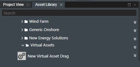
When selected the virtual asset shows up and when dragged into the viewport the property page will show the assigned Metadata that you can edit.
Clone - You can clone a selected Virtual Asset by clicking on the clone icon.
Delete Virtual Asset - Click on the trashcan icon to delete the selected virtual asset. A dialog box will prompt you to confirm as this action in not reversible.
MetaData - This section allows you to search and assign the available metadata definitions to the virtual asset. See the Meta data section for more information.
Connectors Settings
This section allows you to create new Connector types to your account, and you can also assign Metadata definitions for them.
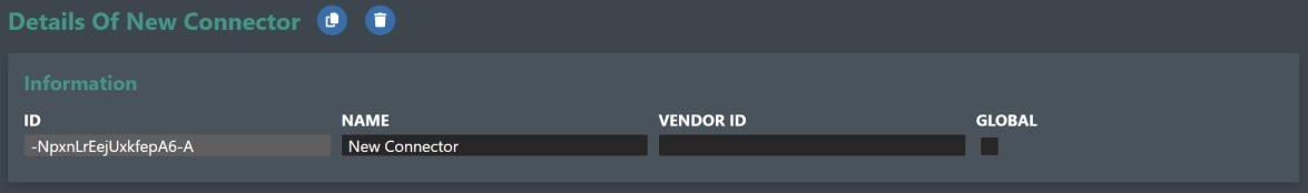
-
ID - This is the unique system ID assigned to the new connector type. Note! This is not changeable.
-
Name - Specify or edit the name for the new connector.
-
VendorID - Use this field to specify your vendor ID if you use one.
-
Global - Check this box if you want to make the Connector Type global for all Accounts.
Clone - You can clone a selected Connector Type by clicking on the clone icon.
Delete - Click on the trashcan icon to delete the selected Connector Type. A dialog box will prompt you to confirm as this action in not reversible.
MetaData - This section allows you to search and assign the available metadata definitions to the connector type. See the Meta data section for more information.
Shape Settings
This section allows you to create new Shape types to your account, and you can also assign Metadata definitions for them.
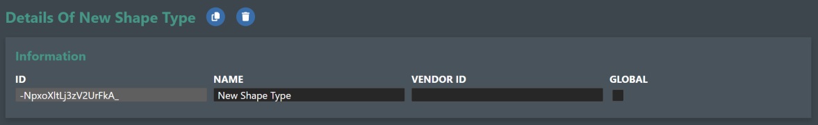
-
ID - This is the unique system ID assigned to the new shape type. Note! This is not changeable.
-
Name - Specify or edit the name for the new shape.
-
VendorID - Use this field to specify your vendor ID if you use one.
-
Global - Check this box if you want to make the Shape Type global for all Accounts.
Clone - You can clone a selected Shape Type by clicking on the clone icon.
Delete - Click on the trashcan icon to delete the selected Shape Type. A dialog box will prompt you to confirm as this action in not reversible.
MetaData - This section allows you to search and assign the available metadata definitions to the connector type. See the Meta data section for more information.
Assets Settings
This section allows you to assign available Metadata for your asset library or to view/edit asset Connector information. Select an asset from the tree view to display the Asset Details as shown below:
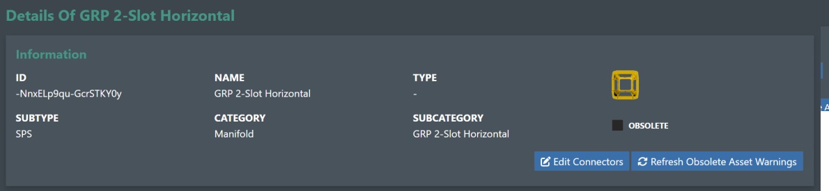
-
ID - This is the unique system ID assigned to the new connector type. Note! This is not changeable.
-
Name - Name of the selected asset. Note! This is not changeable.
-
Type - Shows the assiged type e.g. SPS, piping, rig, vessel etc. Note! This is not changeable.
-
Subtype - Shows the assigned asset sub type. Note! This is not changeable.
-
Category - Shows the assigned asset category e.g. Manifold, Template, XMT etc. Note! This is not changeable.
-
Sub-Category - Shows the assigned asset category. Note! This is not changeable.
-
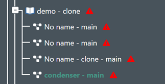
Obsolete - Check this box if the asset is to be marked as obsolete. It will then be refelected that the asset icon in the tree view will change its icon as follows:
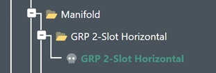
Refresh Obsolete Asset Warnings - If you click on this button, it will mark a list of the projects which the obsolete assets are being used in. They will be marked with a warning sign next to the project names in the project dashboard as shown below:
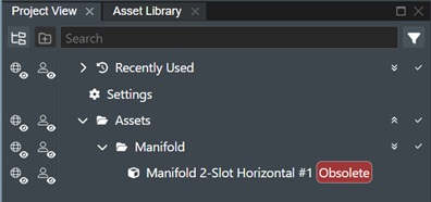
And in Project View you will see the following warning for the asset:
MetaData Definitions - This section allows you to search and assign the available metadata definitions to the asset. See the Meta data section for more information.
Edit Connector
You can also edit the Socket connectors e.g. connection points on the asset. This will display the “Update Sockets Connector” dialog as shown here:
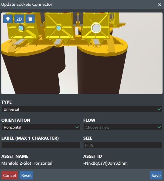
You can use Locate icon to center the asset, 2D icon to switch to 2D view, and Trashcan icon to delete the selected connector.
Use the mouse to zoom/pan/rotate to orient the desiered “Socket Connector” and select it by clicking it. You can then change the following settings:
-
Type - Select the type of connector based on the Connections you have defined from the drop-down list.
-
Orientation - Select either Horizontal or Vertical orientation.
-
Flow - Select either Inlet or Outlet for the socket.
-
Label - Enter a single alphanumerical character to label the socket e.g. 1, A, or similar.
-
Size - Enter a numerical value for the label size.
Press the “Save” button to make the change effective. The “Reset” button will reset the settings to the original defaults. Cancel will abort any changes.